A modular and fully integrated Data Converter Test Solution
The ATX7006A is a fully integrated solution for testing ADCs, DACs and other Analog functions. It combines very high accuracy, low noise and fast sampling with an exceptional ease of use. Traditionally data converters are tested using a whole stack of bench instruments, filters, switch matrices and user made software. Many engineering hours are needed to get reliable results. The ATX7006A is a single instrument for all your data converter testing and test methods.
This means you can concentrate on testing your converters rather than fine-tuning the test set-up. The ATX7006A is capable of testing converters from 4 to 24-bit. Its versatile digital I/O makes interfacing to the DUT easy, even for embedded converters. The Single Reference Architecture improves the stability and reduces calibration effort. The backplane distributed clock ensures coherent measuring.
The ATX7006A is also ideally suited as an add-on upgrade for ATE systems.
Architecture
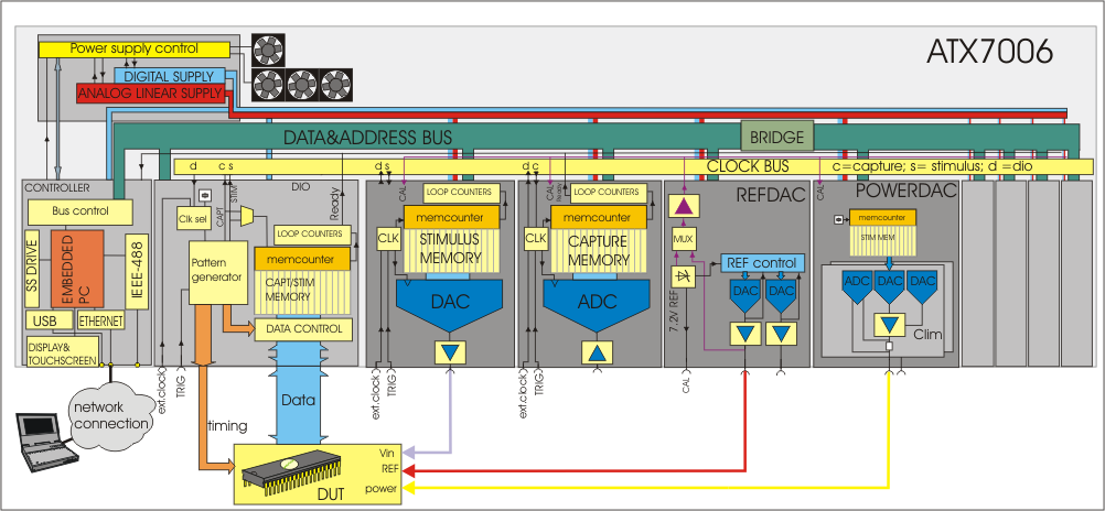
The ATX7006A is a modular system that can be configured according the user's needs. The available Generator and Digitizer modules cover the range from low speed high accuracy testing to high speed medium accuracy testing. Auxiliary modules provide all other signal needs like Reference voltages, Supply voltages, clocks and Digital IO. The ATX7006A measures linearity parameters just as easy as dynamic parameters, all within the same test set-up.
The system controller runs Windows™ embedded and gives the user full access to software features. For production style testing the ATX7006A can run stand alone. For analysis style measurements a PC is used to control the measurement and to display the results. There are three communication possibilities; Ethernet, GPIB and USB. The controller supports the Lua scripting language providing an easy way to add user defined test methods and calculation routines.
The system controller runs Windows™ embedded and gives the user full access to software features. For production style testing the ATX7006A can run stand alone. For analysis style measurements a PC is used to control the measurement and to display the results. There are three communication possibilities; Ethernet, GPIB and USB. The controller supports the Lua scripting language providing an easy way to add user defined test methods and calculation routines.
Performance
The ATX7006A has been designed with one important goal in mind: low system noise. It therefore has linear power supplies for the analog section and thorough Shielding and Grounding to maintain analog signal integrity even in a harsh production environment. The DIO module can provide a low jitter sample clock that is distributed to all other modules and to the DUT.
The standard 20-bit Generator and Digitizer modules offer an outstanding DC accuracy in combination with better than 106dB dynamic performance at sample rates up to 2Msps. The 16-bit modules allow testing up to 400Msps. The ATX7006A features auto calibration and built-in self test.
The standard 20-bit Generator and Digitizer modules offer an outstanding DC accuracy in combination with better than 106dB dynamic performance at sample rates up to 2Msps. The 16-bit modules allow testing up to 400Msps. The ATX7006A features auto calibration and built-in self test.
Capabilities
Linearity
- Offset error, Gain error, Full scale error
- INLE, DNLE, TUE, Transition noise (jitter)
Dynamic
- SNR, SINAD, ENOB
- THD, SFDR, Peak Spurious, PSRR
Software
The ATX7006A is a command driven system that can easily be controlled from almost any programming environment. With ATCom commands can be sent and results read. This allows testing command sequences before implementing them in software. LabView drivers are also available.
When saving test results all settings are included. So when reviewing the results later, there never has to be any doubt about the exact conditions. Results and settings are stored in human readable XML format which allows easy user processing. Export in CVS format is possible and graphs can be saved in graphical format for easy importation into reports.
ATView
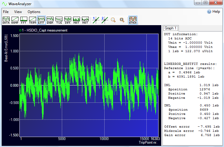
The ATX7006A comes with ATView, a sophisticated software package for configuring, programming and controlling the ATX7006A and analyzing the results. Setting up a test is just a matter of filling in the fields of the instrument panels, program a digital pattern if applicable, and press the START button. After a test the results are viewed in the WaveAnalyzer. The WaveAnalyzer can show the results of time domain, frequency domain and histogram tests. Zoom, stack, and cursor functions are available at any level.When saving test results all settings are included. So when reviewing the results later, there never has to be any doubt about the exact conditions. Results and settings are stored in human readable XML format which allows easy user processing. Export in CVS format is possible and graphs can be saved in graphical format for easy importation into reports.
Test Methods
All standard data converter test methods are supported. Dynamic parameters are measured with sine waves and the results can be analyzed in time domain as well as in frequency domain. Static parameters can be measured with direct ramp testing or with histogram testing. Histogram testing is supported for ramp, triangle and sine wave signals.Key Features
- Fully integrated data converter test solution
- Sample rates from DC up to 200/400MHz
- Unsurpassed signal quality and accuracy
- Coherent measuring by default
- Flexible and versatile digital IO
- Extended Analysis software included
- Static, Dynamic and Histogram testing
- Lua script for easy user test implementation
Technical Specifications
General specifications
- 19" Case Frame, 4U high, with integrated air cooling
- Power supplies, 115 / 230VAC
- Controller module running Windows™ embedded
- Ethernet, USB and GPIB communication ports
- Built-in signal generation and error calculations for production measurements
- ATView Analysis software for Engineering and Qualification purposes (for Windows PC)
Arbitrary Waveform Generator Modules
| AWG22 | AWG20 | AWG18 | AWG16 | |
|---|---|---|---|---|
| Resolution / Update rate | 22 bit / 2 MS/s | 20-bit / 2 MS/s | 18 bit / 300 MS/s (600 MS/s, 1.2 GS/s)* |
16 bit / 400 MS/s (DIO II or ext.clock)* |
| Pattern memory depth | 4M-words | 4M-words | 8M-words | 8M-words |
| Output ranges (Vpp, SE) | 80 mV to 10.20 V in x2 steps | 80 mV to 10.24 V in x2 steps | 580 mVpp to 6.56 Vpp in 8 range | 480 mVpp to 5.12 Vpp in 8 ranges |
| Filters / DC offset voltage | 8 filters (max.) / -5.1 V to +5.1 V |
8 filters (max.) / -5.12 V to +5.12 V |
6 filters / -2.56 V to +2.56 V |
15- 30- 60MHz / -2.56 V to +2.56 V |
| Absolute accuracy | ±(25 µV + 8 ppm of range) | ±(40 µV + 10 ppm of range) | ±(300 µV +0.02 % of range) | ±(500 µV +0.08 % of range) |
| Non Linearity (INL) | ±3 ppm of range (1.5 ppm typical) | ±8 ppm of range (4 ppm typical) | ±0.004 % of range | ±0.003 % of range |
| THD / SNR | -111 dB / 97 dB (@ 1 kHz) | -108 dB / 92 dB (@ 1 kHz) | -99 dB / 73 dB (@ 10 MHz) | -87 dB / 70 dB (@ 1MHz) |
*Update rates > 200MHz require DIO II or an external clock source
Waveform Digitizer Modules
| WFD22 | WFD20 | WFD16 | |
|---|---|---|---|
| Resolution / Sample rate | 22 Bit / 1 MS/s | 20 Bit / 2 MS/s | 16 Bit / 180 MS/s |
| Capture memory depth | 32M-words | 4M-words | 8M-words |
| Input ranges (Vpp) | 0.425 V to 10.20 V in 10 ranges | 0.544 V to 8.16 V in 8 ranges | 0.512 Vpp to 7.688 Vpp in 16 ranges |
| Filters | 500 kHz, 250 kHz, 40 kHz | 800 kHz, 250 kHz, 40 kHz | 15- 30 MHz 60 MHz |
| DC offset voltage | -5 V to +5 V | -5 V to +5 V | equal to input range |
| Absolute accuracy | ±(25 µV + 10 ppm of range)/ ±(25 µV + 15 ppm of range) |
±(40 µV + 10 ppm of range) | ±(800 µV + 0.1 % of range) |
| Non Linearity (INL) | ±3 ppm of range (1.5 ppm typical) |
±8 ppm of range (3 ppm typical) |
±0.006 % of range |
| THD / SNR | -115 dB / 110 dB (@ 1 kHz) | -110 dB / 105 dB (@ 1 kHz) | -89 dB / 70 dB (@ 1 MHz) |
DC Modules
| DRS20 | DPS16 | |
|---|---|---|
| Outputs / res. / settl. | 2 ch. / 20 Bit / 20 ms | 2 ch. / 16 Bit / 10 ms |
| Output range / config. | ±10 V / 2 or 4-wire | ±12 V / 2 or 4-wire |
| Accuracy | ±(25 µV + 10 ppm. Vout) | ±(4 mV + 0.2 %. Vout) |
| Noise (DC- 100 kHz) | 5µ Vrms (typical) | 18µ Vrms (typical) |
| Output current | 10 mA | 200 mA |
| Voltage readback | 24 Bit (DVM function) | 16 Bit (volt & current) |
| V-out modulation | n.a. | 1 mHz - 1 kHz |
DIO Module
| DIO II | |
|---|---|
| Data In- Outputs | 20 / 24 Bit, parallel, byte-byte, serial |
| Capture & Stimuli memory | 8M-word x 16 or 4M-word x 24 Bits |
| Max. data & clock rate | 50 MHz LS mode / 200 MHz HS mode |
| DIO II max. clock rate | 600 MHz on backplane / 1 GHz front |
| Digital I/O levels | 1.2 V - 3.3 V / 5 V CMOS & LVDS |
| Clock jitter (DIO II) | 190 fs (typical @ 100 MHz) |


